TOC Notes
All Topics (10)
- 1. Why Study Theory of Computation?
- 2. What is Computation?
- 3. Subject of TOC
- 4. Terms Used in Theory of Computation (TOC)
- 5. Kleene Star, Kleene Plus, and Language
- 6. What is Automata.
- 7. Types of Automata
- 8. Finite Automata (FA)
- 9. Representation of Finite Automata
- 10. Types of Finite Automata
6. What is Automata.
Automata is an automatic machine which is programmed by a developer to perform a desired computational task. It uses only given input and produces output without knowing the internal process.
or
An automata is a system (abstract machine) which transforms information/data by performing some internal function with different states at different instants of time and produces output without human participation.
Characteristics of Automata
1) Input :-
Set of input symbols from given alphabet (Domain)
Σ = {I₁, I₂, I₃ … In}
2) Output :-
Set of output symbols (Range)
O = {O₁, O₂, O₃ … On}
3) State :-
At any instant of time, automata can be in only one state
Q = {q0, q1, q2 … qn}
4) State Relation (Transition Function) :-
Relation between states with respect to input symbol
δ(q, input) → next state
5) Output Relation :-
Output is associated with state or input
Types of Output Machines
i) Moore Machine :-
The automata in which output is associated only with state.
ii) Mealy Machine :-
The automata in which output is associated with both state and input.
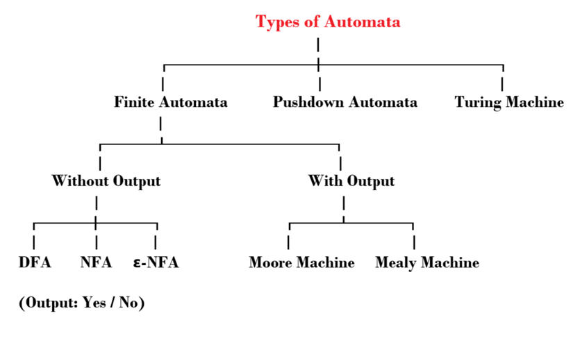
7. Types of Automata
8. Finite Automata (FA)
Basic Idea
A Finite Automaton is a machine that:
- Takes input (like 0 and 1)
- Processes it step by step
- Gives output:
✔ Accept (Yes)
✖ Reject (No)
Real-Life Example
Think of a password system:
- Correct password → Accepted
- Wrong password → Rejected
This behaves like a finite automaton
Definition 1:
A machine that has a finite number of states is called a finite automaton.
Definition 2:
A finite automaton is a computational model consisting of a finite set of states that processes input and changes states accordingly.
Formal Definition
A Finite Automaton is defined as:
M = (Q, Σ, δ, q₀, F)
Components Explained
1) Q (Set of States)
- All possible positions of the machine
- Example:
Q = {q0, q1}
At any time, the machine is in only one state
2) Σ (Sigma – Input Alphabet)
- Set of input symbols
- Example:
Σ = {0, 1}
3) δ (Delta – Transition Function)
- Tells how the machine moves from one state to another
Written as:
δ(q, input) → next state
Example:
δ(q0,1) = q1
4) q₀ (Initial State)
- Starting state of the machine
- Example:
q₀ = q0
5) F (Final States)
- Set of accepting states
- Example:
F = {q1}
If the machine ends in this state → Accepted
Important Concept
Finite Automata are used to recognize a language
That means:
- If a string follows the rules → Accept
- Otherwise → Reject
Example
Problem:
Language L = Strings with odd number of 1’s
Alphabet:
Σ = {0, 1}
Step-by-Step Construction
States
- q0 → even number of 1’s
- q1 → odd number of 1’s
Initial State
q0 (because initially count = 0 → even)
Final State
q1 (because we want odd number of 1’s)
Transition Table
| Current State | Input | Next State |
|---|---|---|
| q0 | 0 | q0 |
| q0 | 1 | q1 |
| q1 | 0 | q1 |
| q1 | 1 | q0 |
How It Works (Step-by-Step)
Example 1: "111"
Start at q0
→ input 1 → q1
→ input 1 → q0
→ input 1 → q1
Final state = q1
✔ Accepted
Example 2: "11"
Start at q0
→ 1 → q1
→ 1 → q0
Final state = q0
✖ Rejected
Example 3: "0111"
Start at q0
→ 0 → q0
→ 1 → q1
→ 1 → q0
→ 1 → q1
Final state = q1
✔ Accepted
9. Representation of Finite Automata
As we know, we construct finite automata to recognize a language. So we can represent finite automata by using:
- Transition Graph / Transition State Diagram
- Transition Matrix / Transition Table
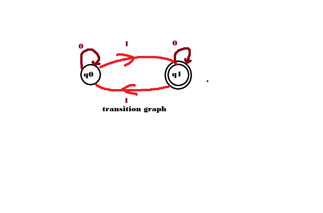
1) Transition Graph / Transition State Diagram
It is a finite directed labeled graph in which each vertex or node represents a state, and the directed edges indicate the transition state.
- Edges are labeled with input symbols.
- It shows how the automata moves from one state to another.
Notations Used in Transition Graph
1. Circle (◯)
A circle represents states.
Example: q0, q1, q2
2. Initial/Start State ( →◯)
A state represented by a circle with an empty arrow pointing to it is called the initial/start state.
Example:
Here, q0 is the start state.
3. Final/Accepting State
A state represented by a double circle is called the final/accepting state.
Example: ((q1))
Here, q1 is the accepting state.
4. Transition
A directed edge with an input symbol “a” indicates the transition of state qi to qj upon receiving input “a”.
Example: qi ----a---> qj
Meaning:
- Current state = qi
- Input symbol = a
- Next state = qj
Example 1: Set of All Strings Containing an Odd Number of 1s
In this DFA, the state changes only when a ‘1’ is encountered. An even number of 1s keeps the machine in the initial state, while an odd number moves it to the final state.
States
Initial State (q0)
Represents an even number of 1s encountered so far.
Final State (q1)
Represents an odd number of 1s encountered so far.
Transitions
1. Transition on Input 0
Zeros do not change the count of 1s.
q0 --0→q0
2. Transition on Input 1
First ‘1’ (odd) moves to the final state.
q0 --1→q1
Second ‘1’ (even) moves back to the initial state.
q1--1→q0
Transition Diagram
              1
        +-----------+
        |           v
     ->(q0) -----> ((q1))
       ^  |          |  ^
       |  |0         |0 |
       |  +----------+  |
       +-------1--------+
Transition Table
| Present State | Input 0 | Input 1 |
|---|---|---|
| q0 | q0 | q1 |
| q1 | q1 | q0 |
Working of DFA
Input String: 1011
Step 1:
Start from q0
Step 2:
Read 1
q0→q1
Step 3:
Read 0
q1→q1
Step 4:
Read 1
q1→q0
Step 5:
Read 1
q0→q1
Final state is q1, which is an accepting state.
Hence, the string is accepted.
10. Types of Finite Automata
Finite Automata are mainly of two types:
- DFA (Deterministic Finite Automata)
- NFA (Non-Deterministic Finite Automata)
1) DFA (Deterministic Finite Automata)
Definition
In a DFA, for every input symbol, the next state of the machine is uniquely determined.
OR
There is only one unique transition from a state for a particular input symbol. Therefore, it is called a Deterministic Finite Automaton.
Since a DFA has a finite number of states, it is also known as a Deterministic Finite Machine.
Characteristics of DFA
1. Deterministic Transitions
Definition:
For every pair of state and input symbol, there exists one and only one transition to the next state.
Mathematical Representation
δ : Q × Σ → Q
Where:
- Q = Finite set of states
- Σ (Sigma) = Input alphabet
- δ (Delta) = Transition function
This means that for every state in Q and every input symbol in Σ, the transition function δ leads to exactly one unique next state.
2. Language Recognition
- DFA recognizes regular languages only.
- Every language that can be represented by a regular expression can also be recognized by a DFA.
- DFA cannot recognize languages that are not regular.
3. Computational Model
- DFA is one of the simplest models of computation.
- It has a finite number of states.
- Its memory is limited to these states only.
- DFA cannot store extra information or count indefinitely.
- It is less powerful than models such as:
- Pushdown Automata (PDA)
- Turing Machines (TM)